

Threaded Reinforcing Bar Socket Fabrication Methods for Reliable Structural Connections
2026-08-30
In the world of reinforced concrete, the weakest link often hides in the connection, not the steel itself. Threaded reinforcing bar sockets have quietly become the backbone of modern seismic and high-rise construction, yet their fabrication tolerances can make or break a structure's ductility. From CNC thread rolling to post-installation grouting, each manufacturing choice ripples into long-term reliability. Sinou has been studying these methods closely, and what we've found may change how you detail your next splice.
Selecting Bar Stock That Survives Repeated Loading
Fatigue failures in bar stock rarely announce themselves with visible deformation—they accumulate quietly at stress concentrations, surface imperfections, or internal inclusions until a crack reaches critical size. When the load cycles run into the millions, the difference between a bar that lasts and one that snaps often comes down to choices made long before machining. Material cleanliness matters more than raw strength: vacuum degassed or electroslag remelted steels reduce the nonmetallic inclusions that act as crack initiation sites, while microalloyed grades with fine grain size push the endurance limit upward. For rotating or reversed bending, look beyond the mill certificate’s tensile numbers and ask for fatigue data, even if it means specifying a slightly lower strength alloy with better crack growth resistance.
Geometry and surface condition can outweigh alloy selection in real parts. Sharp fillets, deep tool marks, or even a poorly radiused keyway can cut fatigue life by an order of magnitude, so bar stock should be specified with enough stock allowance for generous radii and a final finish better than 1.6 µm Ra in high-stress zones. Cold drawn bars carry residual compressive stresses at the surface that help delay crack initiation, but only if subsequent machining doesn’t strip that layer away. If the design allows, consider a turned and polished bar over a black bar—removing the decarburized skin eliminates a weak, soft layer that invites early cracking under cyclic tension.
For critical components, statistical reliability enters the picture. Specify bars from a single heat and require documented control of sulfur, phosphorus, and hydrogen, since even trace hydrogen can cause delayed cracking under sustained or fluctuating load. Shot peening, fillet rolling, or induction hardening can push fatigue strength higher, but only when the base bar steel has low inclusion content and the surface treatment is applied after all stress-raising features are machined. If the application involves corrosion or elevated temperature, the fatigue limit concept becomes murky—test coupons under realistic conditions, because a polished lab specimen will not predict how a hot-rolled bar behaves when pitted or oxidized in service.
Thread Forming Techniques for Deformed Reinforcing Bars
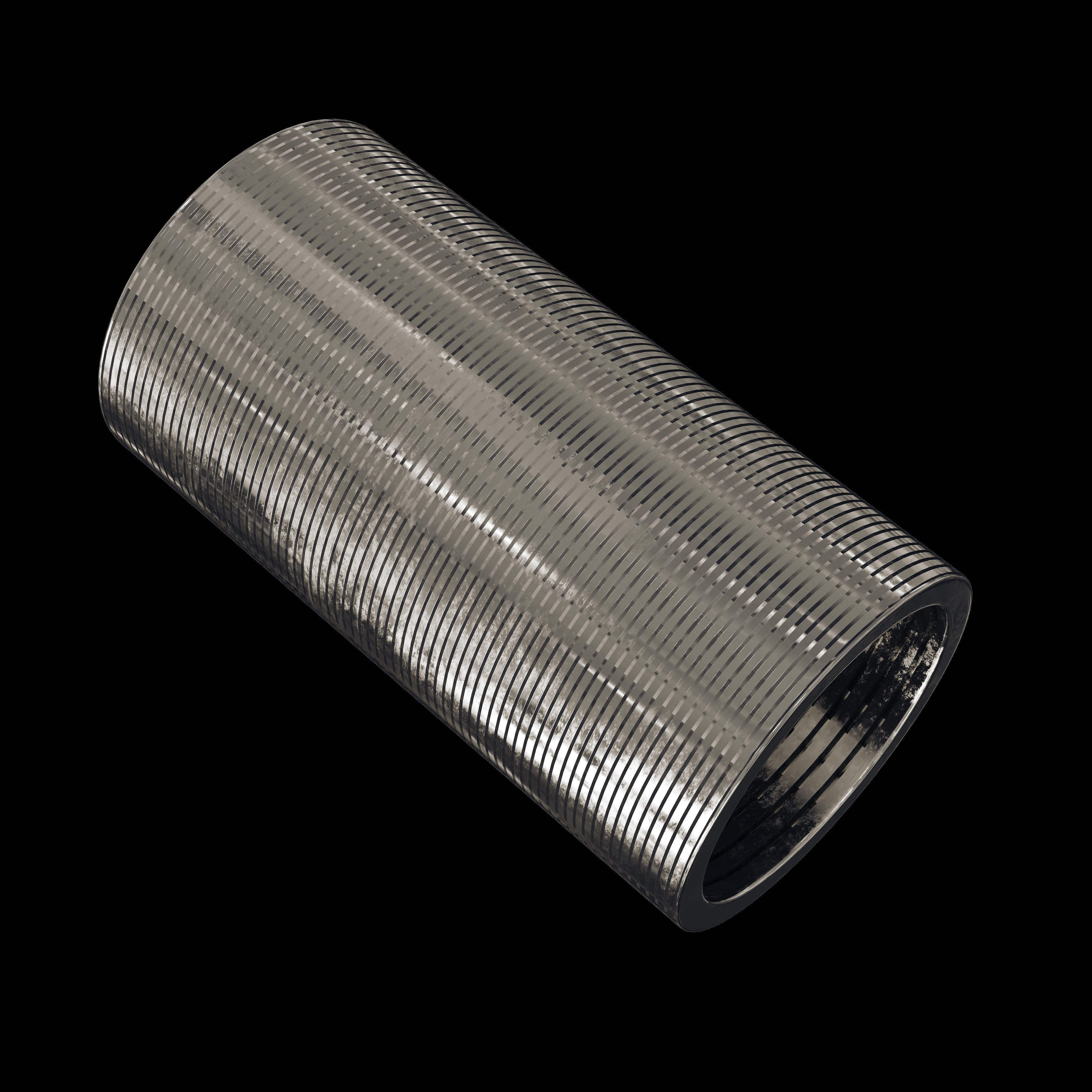
Cold rolling is the dominant thread forming method for deformed reinforcing bars because it works with the bar's irregular rib pattern rather than against it. Before rolling, the bar end is typically peeled or shaved over a short length to create a uniform cylindrical surface, removing just enough of the ribs to allow the rolling dies to engage cleanly. The rolling process then displaces metal under high pressure to form the thread profile without cutting, which keeps the grain flow intact and significantly improves fatigue resistance compared to machined threads.
When tighter dimensional tolerances are required for couplers or anchorages, a two-stage approach is often used. The deformed bar is first rotary swaged or machined down to a smooth diameter, after which threads are cut with a single-point tool or a die head. This gives excellent pitch diameter control and a clean thread finish, but the cutting operation interrupts the longitudinal grain structure at the thread roots, reducing the static and cyclic load capacity to some extent. In practice, the choice between rolling and cutting usually hinges on whether the splice must develop the full ultimate tensile strength of the bar or only a reduced service load.
Portable thread rolling machines have made on-site threading increasingly practical. These compact units clamp directly onto the bar end and use segmented dies that can accommodate minor variations in bar diameter and rib height. The threads produced this way are commonly paired with proprietary mechanical splices, and field inspection typically checks thread flank angle, pitch diameter, and the absence of folds or laps on the flanks. For larger diameter bars or high-strength grades, preheating is sometimes applied before rolling to reduce die wear and prevent surface cracking, though this adds a step that many contractors prefer to avoid when possible.
Tolerance Control in Socket Machining
Maintaining tight tolerances in socket machining starts well before the spindle fires up. The raw stock itself often carries subtle dimensional drift from the mill, so we measure incoming blanks with micrometers and dial indicators rather than assuming nominal dimensions. Even a few tenths of variation in bar diameter can shift how the cutting tool engages, snowballing into out-of-spec sockets by the final pass. Instead of relying on a single reference point, we map the stock at three positions along its length and compensate tool offsets accordingly. This proactive approach prevents tolerance stack-up before it ever reaches the chuck.
Inside the machining cycle, thermal growth plays a quieter but equally critical role. As the spindle warms up, the entire tool assembly expands, moving the theoretical cutting edge away from the programmed position. On longer runs, we pause every twenty to thirty parts for a quick check against a known master socket, then adjust offsets in micron-level increments. Cutting fluid temperature matters too — letting the coolant drift more than a couple of degrees affects both tool stiffness and workpiece contraction. Simple chiller loops on the tank have cut our dimensional variation by nearly half compared to open-loop systems.
Final inspection closes the loop. We no longer accept a single reading from a coordinate measuring machine as gospel; instead, we check radial runout at multiple depths inside the socket bore and compare those values against a go/no-go gauge that mimics actual assembly conditions. Any batch showing more than 0.005 mm drift from the mean gets flagged for immediate tool replacement or offset correction. This tight feedback between measurement and adjustment keeps socket tolerances within a band that looks easy on paper but demands constant attention in practice.
Heat Treatment Cycles That Avoid Brittle Threads
Threaded fasteners that end up glass-hard after quenching are a familiar headache. The fix usually involves tempering at a temperature high enough to trade some surface hardness for toughness, but not so high that the thread loses its ability to resist deformation. For medium-carbon and low-alloy steels, a temper around 450–600°C often lands in the sweet spot, pulling hardness down into the mid-30s to low-40s HRC while keeping the root of the thread from cracking under assembly torque.
Austempering offers a more controlled path when conventional quench-and-temper leaves too much scatter in the results. By quenching into a salt bath held just above the martensite start temperature and holding until the structure transforms to bainite, the thread gets a tough, relatively uniform microstructure without the sharp hardness gradients that invite brittle failure. This works especially well for smaller fasteners where distortion and residual stress are harder to manage.
For case-hardened threads, the main risk is a brittle white layer or excessive case depth at the root. Reducing carburizing time or using a lower carbon potential near the end of the cycle prevents the thread flanks from becoming fully martensitic. A final diffusion step followed by a low-temperature stress relief at 150–200°C can keep the surface hard enough for wear while giving the core enough give to avoid sudden fracture.
Assembly Verification Without Over-Torquing
Modern assembly lines often rely on torque as a proxy for clamp load, but that assumption breaks down when friction varies. A fastener can reach its specified torque while the joint is still loose, or worse, pass beyond safe stress levels without any visible sign. Verification methods that look only at final torque values can easily miss both conditions, so the focus shifts toward monitoring the slope of the torque-angle curve during rundown. A sharp flattening followed by a steep rise often indicates the joint has seated and is entering the elastic clamping zone, giving operators a clearer yes/no signal before excessive rotation causes permanent deformation.
One practical approach uses angle-based windows paired with a torque ceiling. The tool stops at a modest torque limit, but the control system confirms that the angular displacement from the snug point falls inside an acceptable band. If the angle comes up short, the screw may be cross-threaded or bottoming out early; if it overshoots, the mating parts might be compressing a soft gasket or the threads could be yielding. Either outcome triggers a rework station instead of pushing the joint harder. This keeps verification tied to how the joint actually behaves rather than to a single number that can drift with coating, temperature, or lubrication.
For brittle materials or thin-walled housings, even a correctly calculated torque can produce micro-cracks that only show up later as field failures. There, assembly teams increasingly rely on clamp-load estimation through ultrasonic bolt stretch sensors or by measuring the reaction force on a load cell beneath the part. These direct measurements let the line stop exactly at the target preload, not at a derived torque value. Combined with a go/no-go check on final angle, the process confirms the joint is both fully seated and safely within its elastic range, eliminating the guesswork that leads to over-torquing.
Evaluating Slip Resistance in Coupled Connections
Slip resistance in coupled connections is rarely a single number you can pull from a catalog. The actual behavior depends on the interplay between bolt tension, faying surface condition, and the fit of the coupling components. When you start evaluating these joints, the first thing to look at is whether the connection transmits load through friction or through bearing. In many industrial assemblies, the design intent is friction-type slip resistance, but field practices like over-torquing, contamination, or paint overspray can quietly shift the mechanism away from what the engineer assumed.
A practical evaluation usually involves three layers: measured clamping force, surface preparation records, and short-duration slip tests under realistic loading. Clamping force is not simply the torque applied, because thread condition and lubrication can change the relationship by 20% or more. Surface preparation matters just as much. A clean, blast-cleaned faying surface with a known slip coefficient will behave differently from a mill scale surface or one that has been galvanized and then coated. Rather than relying on generic values, it is worth measuring the slip coefficient for the specific coating and roughness you actually have.
When field observations show signs of fretting, rust bleeding from the joint, or loosening after load cycles, these are strong signals that slip resistance has been underestimated or degraded. In such cases, evaluation shifts from prediction to verification. You may need to compare the joint’s remaining clamping force against the applied shear demand, or run controlled tests on identical coupons taken from the same lot of materials. The goal is not just to label the connection as safe or unsafe, but to understand whether the critical contact surface still delivers the friction capacity that the original calculation assumed.
FAQ
Most sockets are produced either by machining from solid steel bar or by cold forging followed by finish machining. The choice hinges on production volume and the required thread precision, with cold forging offering better grain flow around the threads but requiring higher initial tooling investment.
Parallel threads provide a more uniform stress distribution along the engaged length, reducing the chance of localized yielding. They also simplify field assembly because the bar can be fully screwed into the socket without relying on a specific torque to lock the taper.
Thread pitch diameter, lead accuracy, and the concentricity between the threaded bore and the outer socket body are the most critical. Even minor eccentricity can introduce bending stresses under axial load, undermining the connection's reliability.
Sockets are usually made from medium-carbon or alloy steels with tensile properties exceeding those of the connected bar. Fabrication methods must account for the material's machinability and tendency to work-harden, especially when threading after heat treatment, to avoid micro-cracks at the thread roots.
Manufacturers typically carry out monotonic tensile tests to confirm the assembly fails in the bar rather than the socket, plus cyclic tests to evaluate fatigue life. Dimensional inspection with thread gauges and magnetic particle testing for surface defects are also routine before batches are released.
Cold forming displaces the steel rather than severing its grain structure, creating threads with higher surface hardness and residual compressive stress at the roots. This can improve fatigue resistance and reduce the likelihood of crack initiation under repeated load.
Galling occurs when metal surfaces under high pressure adhere and tear during tightening, especially with stainless or coated bars. Fabricators mitigate this by controlling thread surface roughness, applying anti-galling coatings, or specifying a slight clearance on the thread flanks to reduce frictional heat.
The engaged thread length must be sufficient to develop the full tensile capacity of the reinforcing bar without premature thread stripping. Fabrication methods often involve optimizing the socket's internal thread length through finite element analysis and full-scale pull-out tests, rather than relying solely on rule-of-thumb ratios.
Conclusion
Fabricating threaded reinforcing bar sockets that hold up under real structural loads demands more than just cutting a standard thread. The bar stock itself has to be chosen with fatigue in mind; deformed bars often carry surface imperfections and residual stresses from rolling, so a plain carbon grade that machines cleanly may still fail after repeated load cycles if inclusions or microcracks sit near the root of the thread. Thread forming, rather than cutting, can shift material instead of removing it, which preserves the bar's cross-section and often improves fatigue resistance, but only when the die geometry accounts for the irregular ribs of deformed reinforcement. Socket machining tolerances then become the second line of defense: a thread that is too loose concentrates stress on a few engaged flanks, while a fit that is too tight can crack the socket during installation. Heat treatment needs careful sequencing too. Quenching and tempering after machining can leave a hard, brittle case on the thread crests unless the tempering temperature is held in a narrow band, because even small variations in carbon content across a batch of rebar will change the martensite formation.
On the assembly side, torque control is often misunderstood. The goal is not maximum clamping force but repeatable preload that keeps the coupled bars from slipping under cyclic tension. Over-torquing a threaded socket can yield the thread roots, creating a plastic hinge that feels tight during installation but loosens after a few load reversals. A better approach pairs torque with angular rotation checks, or uses direct tension indicators, so that the joint is verified without relying on a single wrench setting. Slip resistance in coupled connections then depends on how well the socket grips the bar; a smooth machined thread with tight tolerances may still allow micro-movement if the contact surfaces are too polished. Light knurling or a controlled phosphate coating can raise the friction coefficient just enough to prevent slip without introducing notch sensitivity. Field testing has shown that connections which pass a low-amplitude cyclic slip test before full loading tend to retain their stiffness far longer than those that are merely torqued to spec. This means the fabrication method, from bar stock selection to final surface finish, has to be treated as one continuous system rather than a set of isolated operations.
Contact Us
Contact Person: HaiYan
Email: [email protected]
Tel/WhatsApp: +86 18957325588
Website: https://www.senyoubeton.com/