

Servo Motor Magnets Company Guide to Selecting High-Quality Magnets
2026-09-08
When a servo motor loses precision, the root cause is rarely the controller—it’s usually the magnet. High-quality servo motor magnets determine torque density, cogging smoothness, and thermal endurance, yet many buyers still choose based on price alone. This guide from DAWA strips away the guesswork. You’ll discover what separates a truly high-performance magnet from a commodity alternative: raw material grade, magnetic field consistency, coating integrity, and dimensional tolerance. Whether you’re prototyping a compact robot joint or qualifying a supplier for high-volume automation, the decisions you make here will directly shape motor reliability and lifespan. Don’t let a hidden magnet flaw become your next field failure. Read on to see how the right selection criteria—and the right magnet partner—can elevate your servo motor design before the first prototype spins.
The Real Cost of Cutting Corners on Servo Motor Magnet Quality
When procurement teams push for cheaper servo motor magnets, the savings on paper rarely survive contact with the production floor. Lower-grade magnetic materials lose flux density faster under thermal cycling, forcing drives to compensate with higher current. That extra current shows up as wasted heat, shorter winding insulation life, and a motor that no longer hits its rated torque curve after a few thousand hours. The result is not just a softer axis response but a machine that drifts out of spec on precision jobs, creating scrap parts and intermittent faults that are notoriously hard to trace back to the magnet.
There is also the hidden cost of inconsistency. Budget magnets often come with wider tolerances on coercivity and remanence, so two motors from the same batch can behave differently under load. One axis holds position rock steady while another oscillates around the target, and suddenly the entire motion system needs derating to accommodate the weakest link. Field service calls multiply, warranty claims rise, and the engineering team spends weeks chasing problems that a higher-grade magnet would have never introduced.
The real expense, though, is trust. A servo motor is expected to run for a decade in harsh industrial environments. When magnet quality is sacrificed, that lifespan shrinks to a fraction, and the replacement costs—downtime, labor, lost production—dwarf any initial purchase discount. Smart buyers eventually learn that the cheapest magnet is the one you never have to replace.
Understanding Coercivity and Why It Decides Whether Your Motor Survives Overload
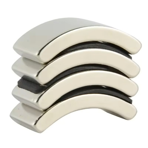
Coercivity is the magnetic field strength required to reduce the magnetization of a permanent magnet to zero after it has been saturated. In practical terms for motors, it measures how stubbornly a magnet clings to its magnetic orientation when an opposing field tries to flip it. This property is not just a datasheet number; it acts as the hidden safety margin that determines whether the rotor magnets can shrug off a sudden current spike or quietly lose their strength the first time the drive pushes beyond nominal torque.
When a motor experiences overload, the stator windings carry far more current than usual, and that current generates a powerful demagnetizing field aimed straight at the rotor magnets. If the magnet's coercivity is too low—common in cheaper grades or after sustained high-temperature operation—the field can punch through and irreversibly flip entire magnetic domains. The result is a partial or total loss of flux, which shows up as reduced torque constant, higher no-load speed, and a motor that runs hotter while doing less work. Once this happens, simply reducing the load does not restore the original performance; the damage is permanent and usually gets worse with every subsequent overload event.
Designers get around this by specifying magnets with elevated coercivity grades, such as neodymium variants labeled H, SH, UH, or EH, which trade a bit of remanence for a much stronger resistance to demagnetization at high temperatures. The choice matters because coercivity drops as the rotor heats up, and a magnet that looks fine on paper at room temperature can fail badly when the winding temperature climbs past 150°C during a stall or blocked-rotor condition. By keeping the operating point well away from the knee of the demagnetization curve, engineers ensure that an occasional overload does not become a silent killer of motor performance—turning what should be a survivable stress test into a costly lesson in magnetic material limits.
How Temperature Ratings and Demagnetization Curves Predict Field Failures
Temperature ratings on permanent magnets often read like a safety label, but they encode a failure threshold that field data rarely contradicts. When a magnet operates near or beyond its maximum working temperature, the internal alignment of magnetic domains begins to decay at a measurable rate. This isn't an instant collapse; it's a creeping loss of flux density that mimics normal aging until a device simply can no longer deliver the required torque, holding force, or signal strength. Technicians who dismiss a 10°C overshoot as negligible are frequently the ones replacing motors or sensors months later without understanding why.
Demagnetization curves provide the visual evidence for that gradual failure. Plotted in the second quadrant of the B-H plane, these curves change shape with temperature—especially around the knee point. At room temperature, the curve stays linear well into the operating range. But at elevated temperatures, the knee shifts upward and the curve bends earlier, meaning a magnet that appeared stable at 20°C can be pushed into irreversible loss if the operating load line intersects the curve below the knee. Engineers who overlay the actual working point on high-temperature demagnetization curves can spot designs that are one hot day away from partial demagnetization.
Combining both tools turns guesswork into a predictive routine. In practice, a technician can measure the magnet's field strength after a heat soak and compare it against the demagnetization curve for that specific grade and temperature. A drop of more than a few percent indicates that the magnet has entered the non-linear region and will never fully recover. This approach has caught failing rotor magnets in servo motors and compressor drives before complete breakdown, simply by noticing that the demagnetization curve at 150°C crossed the operating point weeks before the machine overheated. By treating temperature ratings as a curve-shifting input rather than a static limit, field failure patterns become far easier to read and prevent.
Sorting Through Magnetic Grades and Coatings Without Falling for Marketing Hype
A high N-rating on a spec sheet doesn't mean much if the magnet loses strength at your operating temperature. Most neodymium grades only hold their advertised pull force up to about 80°C, and even then the geometry and surrounding steel matter just as much as the raw grade. If a supplier pushes N52 without asking about your heat load or duty cycle, that's a red flag.
Coatings are another area where vague claims hide real differences. A thin nickel-copper-nickel layer might be fine in a dry indoor sensor, but it will flake or corrode quickly in salt air or humid washdown environments. Ask for the exact coating stack, thickness in microns, and salt spray test hours instead of accepting terms like 'rust-proof' or 'marine grade' at face value.
Finally, demand more than a glossy PDF. Reputable vendors can supply pull-force curves at multiple temperatures, coating adhesion test results, and lot-specific inspection data. If the answer is 'we've never had complaints' or they steer you toward a more expensive 'premium' line without explaining what changes physically, you're looking at marketing, not engineering.
What a Magnet Supplier's Test Reports Reveal About Their Process Control
A close look at a magnet supplier's test reports often tells you more than any sales pitch. You can spot whether they're screening for the right parameters—coercivity, remanence, temperature coefficients—or just printing nominal values. When a report includes actual measured data per batch, with lot numbers and date stamps, it usually means the supplier isn't just hoping for the best. You'll notice if they flag deviations instead of burying them, and if they retest after adjustments. That kind of transparency is rare and worth paying attention to.
Process control shows up in the variation between reports. If every sheet lists the same exact number to three decimal places, that's a red flag—real magnets have scatter. A supplier with genuine control will show a range, maybe a histogram or a Cp/Cpk value, and they'll be able to tell you which lot a specific order came from. Look for nonconformance notes, heat treatment records, and coating thickness checks. Those small details indicate someone actually walked the floor and measured things.
Another tell is how they respond when a test falls outside spec. Do they reject the lot, mark it clearly, and trace it back to a furnace run or a raw material shipment? Or does the report conveniently get "corrected"? Suppliers with mature process control don't hide bad results; they document them because they know a magnet that fails one parameter might still work for a different application. That honesty, combined with consistent measurement methods across lots, is the real story in the paperwork.
Designing for Manufacturability When Custom Magnet Shapes Meet Tight Air Gaps
Getting a custom magnet shape to sit reliably inside a tight air gap is less about heroic machining and more about deciding early which tolerances actually drive performance. Non-standard profiles almost always force the magnet supplier to grind or wire-cut after sintering, and those secondary steps become disproportionately expensive when the air gap is narrow. A useful first move is to map the magnetic flux sensitivity across the intended air gap: often a small local radius or chamfer has far more influence than the overall profile, so tightening that one feature while loosening others keeps costs down without sacrificing field strength.
Tooling and assembly constraints deserve equal weight. A magnet with a sharp internal corner may look straightforward in CAD but can crack during pressing or require an electrode so thin that EDM wear becomes unpredictable. For tight air gaps, consider designing in a slight draft or a sacrificial datum surface that can be ground after magnetization if needed. This gives the assembly team a reference plane that does not shift when the magnet is snapped into a housing, reducing the stack-up that quietly eats the gap clearance.
Finally, treat material lot variation as part of the geometry problem. Even a well-machined custom shape can vary in residual induction by a few percent, which changes the flux across the gap. If the design relies on a single nominal dimension, it will fail intermittently. Include a simple go/no-go gap gauge or a reluctance-based check at the prototype stage so that the manufacturing process can be adjusted before full production. The goal is not a perfect magnet, but a repeatable one that fits the gap every time.
FAQ
Focus on magnetic strength consistency, dimensional accuracy, and the supplier's ability to deliver repeatable performance across batches. Also check how the magnets behave under the motor's peak operating temperature and whether they retain flux over time.
Servo motors often run hot, and magnets lose strength as they heat up. A high-temperature grade, like N35SH or N38UH for neodymium, keeps demagnetization low even near 150°C. Without that headroom, torque drops and the motor may need oversizing.
Grade determines both energy product and coercivity. A higher grade can shrink the motor footprint, but only if the coercivity is sufficient to resist demagnetization from stator fields. Matching grade to load and temperature avoids premature failure.
Servo environments can contain moisture, cutting fluids, or mild acids. A nickel-copper-nickel coating gives solid corrosion protection, while epoxy or parylene adds an extra barrier in harsh conditions. The right coating prevents rust that would otherwise cause surface flaking and field loss.
Arc or segment magnets conform to the rotor, reducing air gap variance and improving flux linkage. Custom shapes also allow tighter packing, which can raise torque density without increasing current draw.
Look for ISO 9001 as a baseline, plus IATF 16949 if the motors go into automotive or high-reliability applications. Ask for material test reports, magnetic property data, and dimensional inspection records for each lot.
Tight tolerances on magnet thickness and curvature keep the air gap uniform, which directly affects cogging torque and vibration. Loose tolerances force extra adhesive or machining, adding cost and lowering motor precision.
Conclusion
Cheap servo motor magnets rarely stay cheap once field returns and warranty claims start stacking up. A motor's ability to survive an overload depends heavily on coercivity, not just the maximum energy product printed on a datasheet. If the intrinsic coercivity HcJ is marginal, a sudden current spike or a stalled rotor can partially demagnetize the magnets, and performance drops permanently before anyone notices. Temperature ratings and demagnetization curves are where this risk becomes visible: look at the knee point at the motor's worst-case operating temperature, not the room-temperature curve. A grade that looks fine at 20°C can lose several percent of its flux irreversibly at 150°C if the knee is too close to the operating point.
The same scrutiny should apply to supplier claims. Ask for full test reports from each batch, including coercivity, remanence, and coating adhesion, and check whether the values stay within a tight band rather than drifting from lot to lot. That consistency tells you more about process control than a polished brochure. Magnetic grades and coatings should be chosen for the actual environment: a standard nickel-copper-nickel coating often does the job, but if the motor lives near salt mist or cooling fluid, a thicker barrier or epoxy layer is worth the extra cost. Finally, when custom magnet shapes must fit tight air gaps, involve the magnet supplier early. Small chamfers, realistic tolerances, and a clear magnetizing direction can prevent assembly scrap and magnetic field nonuniformity that would otherwise surface only in end-of-line testing.
Contact Us
Contact Person: Kelvin Lo
Email: [email protected]
Tel/WhatsApp: 0769-88561131
Website: https://dawamagnetic.com/