

Mixer Agitator Fabrication Techniques for Reliable Industrial Mixing
2026-11-16
Ask any plant engineer what keeps them up at night, and unreliable mixing rarely tops the list—until an agitator shaft snaps or a blade cracks mid-batch. The truth is, most mixer failures trace back to fabrication shortcuts: uneven weld penetration, unbalanced impellers, or material mismatches that no amount of maintenance can fix. At Sinou, we take a different route. This post walks through the fabrication techniques that keep industrial mixers running true—so your process stays stable, and your downtime stays low.
Alloy Selection for Corrosive and Abrasive Mixing Environments
In mixing operations where acidic or chloride-laden slurries also carry hard particulates, alloy selection cannot rely on corrosion tables alone. The simultaneous attack from pitting, crevice corrosion, and low-stress abrasion removes protective oxide layers faster than they can reform. This often rules out standard austenitic stainless steels like 304/316, which perform well in clean corrosive fluids but lose too much material under sliding or impingement wear.
Duplex stainless steels such as 2205 or 2507 offer a practical middle ground, combining high pitting resistance with roughly twice the yield strength of 300-series grades. For more aggressive chloride and solids loading, nickel-based alloys like Alloy C-276 or 625 resist localized attack but may require hardfacing or ceramic inserts in high-velocity impact zones. Cobalt-chromium alloys like Stellite 6 or 12 can handle both acidity and galling wear, though they are costly and difficult to machine.
A more effective approach is to separate damage modes where possible: use a corrosion-resistant base material and protect high-wear areas with tungsten carbide overlays, rubber linings, or replaceable wear plates. Field trials under actual mixing intensity and pH swings still matter more than laboratory coupon data, because the interaction between corrosion and abrasion is highly system-specific.
Precision Welding Methods That Keep Agitator Shafts Straight
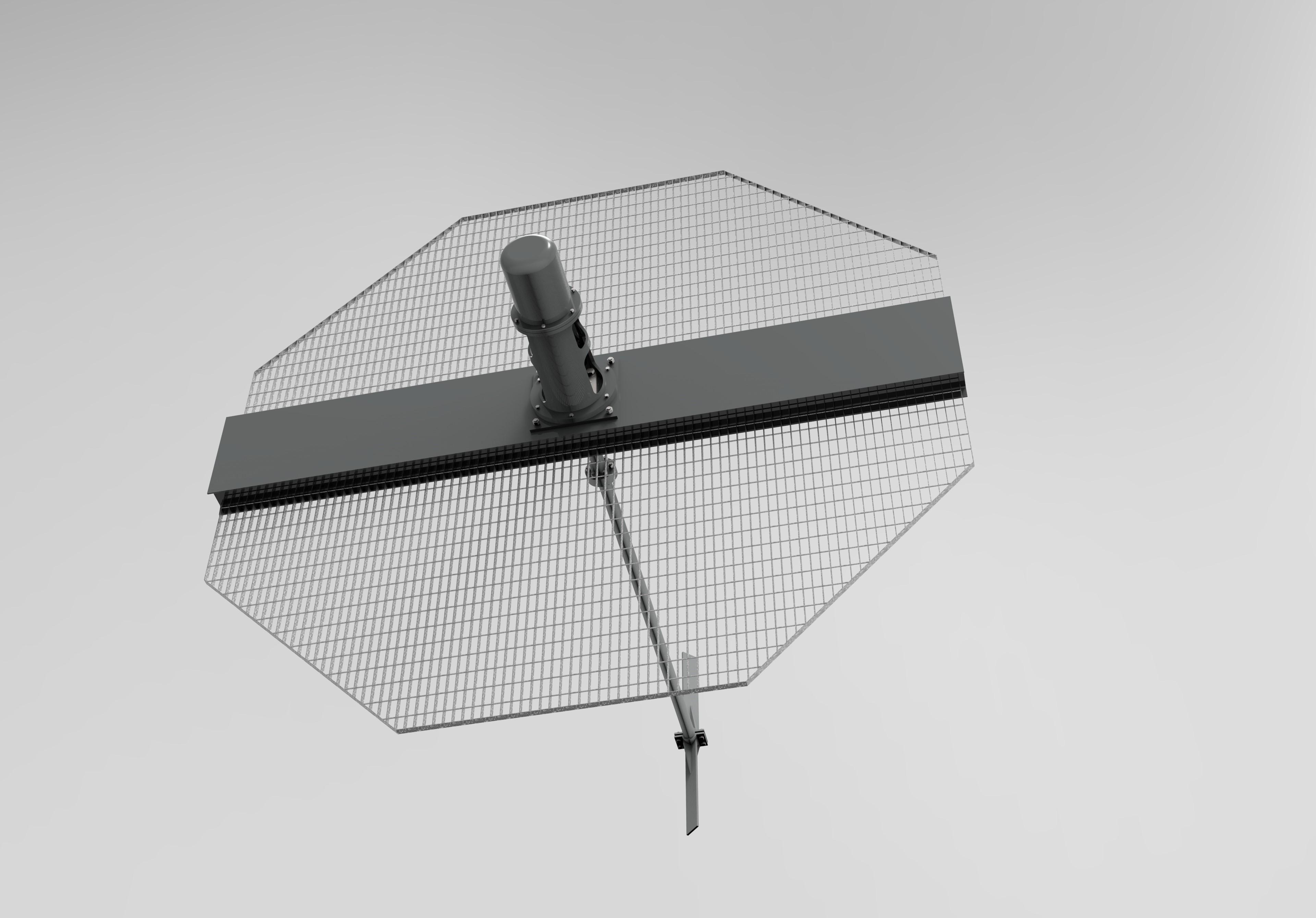
Maintaining straightness in an agitator shaft starts with controlling heat input during welding. A shaft that receives uneven thermal energy will bow, often irreversibly, toward the hotter side. Low-heat-input processes such as pulsed TIG or controlled short-circuit MIG reduce the overall temperature gradient, while symmetric weld sequencing—alternating from one side of the shaft to the other—balances shrinkage forces in real time. Rather than running a single continuous bead down one side, welders typically deposit short sections on opposite faces, allowing the part to cool slightly between passes.
Rigid fixturing also plays a central role. The shaft is clamped into a heavy alignment jig or supported on multiple steady rests before the first arc is struck. This prevents the workpiece from relaxing into a curved shape as residual stresses develop. For long shafts, welders often use a back-step or skip-weld pattern: they start at the middle and work outward, or jump to distant locations to spread heat evenly. After the joint is complete, many shops perform a light thermal stress-relief cycle, heating the shaft slowly to a few hundred degrees and cooling it in still air, which reduces locked-in distortion without sacrificing weld strength.
Verification is the final line of defense. Once the shaft has cooled to room temperature, it is mounted on rollers or V-blocks and a dial indicator is run along several diameters. If runout exceeds the allowed tolerance—commonly 0.001 to 0.002 inches per foot of length—the shaft may be straightened using controlled peening or localized spot heating on the convex side. Some fabricators also use vibratory stress relief to settle the weldment before final machining. The goal is not just an acceptable weld profile but a shaft that rotates true under load, because even a slight bow can lead to premature bearing wear and seal failure in an agitator.
Dynamic Balancing Routines for Low-Vibration Operation
Balancing is not a one-time check but a recurring discipline that adapts to wear, thermal shifts, and load patterns. Start with baseline vibration readings at key bearing points, then compare them after each minor adjustment to the rotor. A common mistake is chasing absolute zero vibration, which ignores that residual unbalance from assembly tolerances and material inhomogeneity will always exist at some level. The goal is to bring the machine into a range where vibration no longer excites structural resonances or accelerates bearing fatigue.
For field work, use a two-plane balancing approach when the rotor length exceeds roughly twice its diameter. Place trial weights at known angular positions, record phase and amplitude changes, and then calculate correction weights using vector methods rather than guesswork. Keep trial weights modest—around 10 to 15 percent of the estimated unbalance—to avoid masking the original response. After each correction, allow the machine to reach steady-state temperature before taking the next set of readings.
Low-vibration operation also depends on how you document and interpret the data. Instead of relying on a single overall velocity value, track the 1X running speed component separately from harmonics and subharmonics. If the 1X component drops but overall vibration remains high, the problem may be misalignment, looseness, or coupling wear rather than unbalance. Record the balancing procedure, trial weight sizes, and final correction locations so that future maintenance can repeat or refine the process without starting from scratch.
Surface Finishing Choices That Reduce Buildup and Contamination
Roughness is almost always the first lever to pull. A surface with deep valleys or sharp peaks gives particles, biofilms, and process residues a place to grip. Polishing to a low Ra value helps, but the target should be driven by the actual service environment rather than a generic mirror finish. In many hygienic applications, an Ra below 0.8 µm on stainless steel makes routine cleaning noticeably more effective without chasing diminishing returns.
Electropolishing goes further by removing a thin layer of metal and smoothing microscopic peaks that mechanical polishing may leave behind. This reduces the true surface area where contaminants can anchor, and for stainless steel it also improves the chromium-to-iron ratio at the surface, which strengthens the passive oxide layer. For non-metallic parts or those that cannot be electropolished, coatings such as PTFE, ceramic, or specialized polymer liners can offer a low-energy, non-porous barrier that resists adhesion and withstands aggressive cleaning cycles.
The right choice is rarely universal. A finish that works for a high-purity water line may fail in a high-temperature food process, where thermal cycling can crack a coating and create new contamination risks. Matching the finish to the fluid chemistry, temperature range, and cleaning method matters more than chasing the lowest possible roughness number. Sometimes a slightly textured but well-passivated surface will outperform a highly polished one that is prone to scratching or corrosion in service.
Impeller Design Trade-offs for Viscous and Shear-Sensitive Fluids
Pumping viscous fluids through a centrifugal impeller quickly exposes a core tension: narrow flow passages improve hydraulic efficiency but impose high shear rates, while wider passages reduce shear but let more fluid slip backward. For products like polymer melts, paints, or cell cultures, designers often choose low-shear impeller geometries—such as open or semi-open vanes with low exit angles—even though this means larger diameters and slower speeds to hit the same duty point.
Shear-sensitive additives complicate matters further. A shrouded impeller with tight sidewall clearances generates strong velocity gradients that can shred long-chain molecules or rupture mammalian cells. Opening those clearances and using fewer, thicker vanes lowers peak shear but weakens the impeller's ability to build pressure, forcing a trade-off between product integrity and pump footprint. In practice, many systems settle on a reduced-speed, high-torque arrangement where the impeller turns just fast enough to move the fluid without crossing the material's shear threshold.
Heat generation adds another dimension. Viscous friction inside the impeller raises fluid temperature, and for temperature-sensitive fluids this can alter rheology or denature proteins long before mechanical damage appears. The impeller design therefore influences not just flow and shear, but also thermal load—a factor often ignored until a batch fails quality control. A well-designed impeller for these fluids typically favors gradual acceleration of the fluid, minimal recirculation zones, and careful selection of blade curvature to balance energy input against product safety.
Factory Testing Protocols That Predict Long-Term Mixer Reliability
Most mixers pass a basic spin test, but that tells you almost nothing about how the gearbox will hold up after 20,000 hours. The protocols that actually matter push the unit through load-cycling sequences that mimic real batching patterns—not just steady-state running. During these cycles, accelerometers mounted on the bearing housings capture vibration signatures, and any change beyond a narrow band flags a misalignment or gear tooth defect before the mixer leaves the floor.
Thermal mapping is another underused predictor. By running the mixer at full torque while monitoring oil temperature rise and heat distribution across the casing, a factory protocol can spot poor lubrication paths or tight clearances that won't show up in a cold test. Some facilities also pull an oil sample right after the hot run and check for early wear metals; a spike in copper or iron often points to a bearing cage or gear face that will fail prematurely.
Seal integrity testing is equally telling. Instead of a simple leak check, a meaningful protocol applies pressure decay measurements on every shaft seal at operating temperature, then repeats the test after a rapid cool-down. Seals that hold at room temperature but weep after thermal cycling tend to fail in the field within the first year. Factories that collect this data over hundreds of mixers can set pass/fail limits that correlate directly with warranty claims and long-term reliability.
FAQ
For hot sulfuric acid, high-silicon stainless steels or Hastelloy C-276 are typical because they maintain a stable passive film. In chloride brines, duplex grades like 2205 or super duplex 2507 resist pitting better than standard 316L.
If the weld heat input is too high, the heat-affected zone becomes brittle and residual tensile stresses remain. Using low heat input processes like pulsed TIG, followed by post-weld heat treatment, reduces these stresses and improves fatigue resistance.
Even a small mass imbalance creates centrifugal forces that grow with the square of speed. This leads to shaft deflection, seal leaks, and bearing damage. Dynamic balancing brings the residual imbalance within acceptable limits so the unit runs smoothly.
Electropolishing is highly effective because it removes surface peaks and embedded iron, creating a microscopically smooth, passive surface. For non-sanitary applications, a fine glass bead blast gives a uniform matte texture that releases sticky products more easily.
They rely on CNC machining centers with in-process probing to check dimensions after each cut. Final verification on a coordinate measuring machine ensures the hub bore and keyway stay concentric with the shaft axis, preventing runout.
Hardfacing is typically applied to the leading edges of impeller blades and the bottom of the hub where abrasive wear is most severe. Depositing a tungsten carbide or Stellite overlay by MIG or laser cladding can outlast the base metal several times.
For long shafts with moderate torque, a fabricated design using heavy-wall pipe and forged flanges reduces weight and cost while allowing internal inspection. Solid machined shafts are reserved for short, high-torque or high-stiffness applications where any weld is a risk.
Full penetration welds are often checked with ultrasonic testing or radiography to detect internal flaws. Surface-breaking defects are found with dye penetrant testing on stainless steel, and magnetic particle inspection is used on carbon steel components.
Conclusion
Fabricating a mixer agitator that holds up under harsh industrial conditions starts well before the first weld bead. Material selection is not a generic checklist item; for corrosive or abrasive service, a metallurgist often pairs a high-nickel alloy shaft with a hardfaced impeller edge, balancing cost against pitting resistance and erosion life. The welding sequence itself becomes a straightness control method—instead of relying on post-weld straightening, skilled fabricators use balanced heat input, short stitch welds, and rotating positioners to keep runout under a few thousandths of an inch. Once assembled, the rotor is dynamically balanced on a soft-bearing machine, not just statically, because residual couple unbalance at operating speed is what tears out gearboxes and cracks baffles. Surface finish is then matched to the product: an electropolished 316L wetted surface resists biofilm and powder caking, while a glass-flake-filled epoxy may be enough for raw slurry duty without the polishing cost.
Impeller geometry is the point where many fabrication shops stumble, because a high-solidity pitched-blade turbine that pumps a viscous polymer may shred a shear-sensitive floc or emulsion. The remedy is not just changing blade angle but rethinking hub design—bolt-on, replaceable blades let a plant shift from a narrow hydrofoil for low shear to a wide, swept-back blade for high viscosity without replacing the entire shaft. Before any mixer leaves the floor, factory testing should mimic real upset conditions: run the agitator dry for a few seconds to check for rub, then in water with a deliberately unbalanced load to confirm the bearing housing temperature stays stable. This combination of material awareness, weld discipline, rotor balancing, surface tailoring, and load-specific testing is what separates a mixer that runs quietly for a decade from one that needs a rebuild every eighteen months.
Contact Us
Contact Person: HaiYan
Email: [email protected]
Tel/WhatsApp: +86 18957325588
Website: https://www.senyoubeton.com/