

Mid-Diameter Fiber Fusion Splicer: A New Type Built for Faster, Cleaner Splices
2026-08-27
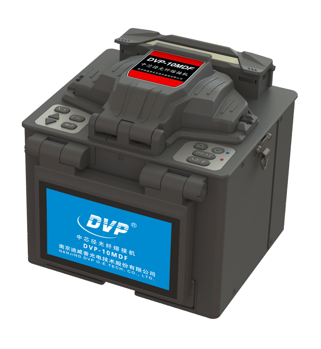
If you've ever dealt with mid-diameter fiber splicing, you'll know the usual compromises: speed, cleanliness, or reliability—pick two. The new DVP mid-diameter fiber fusion splicer refuses to play that game. Engineered for faster, cleaner splices in one streamlined package, it's already turning heads in the field. Curious what sets it apart? Keep reading.
Why Mid-Diameter Fiber Doesn't Splice Like Standard Fiber
Fusion splicers are built around a quiet assumption: both fibers have the same glass diameter. Standard single-mode fiber uses a 125 µm cladding, and the V-grooves, clamps, and imaging routines are all calibrated to that number. Mid-diameter fiber throws that assumption away. With a cladding of 80 µm or 60 µm, the fiber sits loosely in a standard V-groove, tipping or shifting before the arc even fires. The machine's auto-alignment may hunt for an edge that isn't where it expects, and often gives up with a motor error or a blurry core image.
Even when alignment succeeds, the arc parameters don't transfer. Fusion current and duration are tuned for the thermal mass of a 125 µm cladding. A smaller glass diameter heats faster, so the mid-diameter side can overmelt, sag, or form bubbles while the standard side barely softens. Reducing arc power manually helps the small fiber but leaves the standard fiber underfused, producing a weak joint that looks fine on screen and fails later under tension or temperature cycling. Residual stress from mismatched cooling rates adds another slow-failure mechanism.
The practical workaround is rarely automatic. Some splicers have a cladding-diameter preset, but even then the mode-field mismatch may not be corrected. Often a short bridge fiber is spliced to the mid-diameter fiber at low energy first, then that bridge is spliced to the standard fiber using normal settings. Without a preset, technicians fall back on manual electrode offset, shorter arc time, and repeated OTDR checks. It is a reminder that "standard fiber" isn't just a name—it's a set of physical assumptions the machine relies on.
The Clamp and Electrode Changes Behind Faster Cycles
Cycle times in resistance welding rarely hinge on a single factor, but the clamp and electrode assembly often sets the pace. Traditional setups rely on bulky water-cooled electrode holders that take seconds to open, reposition, and reseat after every weld. Newer low-inertia clamp designs shift that balance by reducing the moving mass. Shorter arms, lighter back caps, and integrated air logic let the jaws snap open and closed with far less dwell at both ends of the stroke. Welders notice the difference most in high-mix production, where the same station handles multiple part geometries and every fraction of a second spent waiting for the clamp to settle adds up across a shift.
Electrode geometry and material transitions also play a quiet but oversized role in faster cycling. Copper alloys with higher thermal conductivity pull heat out of the weld zone more efficiently, letting the nugget solidify sooner without risking expulsion. That means the control can trigger the clamp release earlier in the cooling phase. Meanwhile, tapered electrode tips—once standard—give way to flat-face or dome-nose profiles that maintain contact area longer, reducing the frequency of dressing stops that force the line to pause. A well-chosen electrode shape can cut the number of tip changes per shift by half, and every change skipped is a cycle gained.
Field retrofits often reveal how clamp sequencing, not just raw speed, unlocks faster cycles. Instead of waiting for full clamp pressure before initiating weld current, some controllers now ramp force and current in parallel. The electrode touches the part, and within milliseconds the controller begins the squeeze-to-weld transition, trusting the pneumatic system to reach target force during the first few cycles of current. This overlap shaves 100 to 300 milliseconds per weld, which sounds trivial until you multiply it by thousands of parts per day. When paired with quick-change electrode adapters that snap in without wrenches, the entire clamp and electrode subsystem stops being a bottleneck and starts setting the rhythm for the cell.
Cleaner End Faces Without the Usual Alcohol Wipe
Many technicians still reach for alcohol wipes out of habit, but alcohol can leave residue, damage some connector materials, and evaporate too quickly to dissolve stubborn contaminants. A dry cleaning routine centered on purpose-built cassette cleaners or mechanical click cleaners removes debris through physical contact alone, without introducing liquid that could migrate into the ferrule or alter index-matching gels.
For occasional spot cleaning, a reel-based fiber optic cleaner combined with a short blast of filtered, moisture-free air works surprisingly well. The key is to inspect the end face after every pass under a handheld scope. If contamination persists, use a fresh section of the cleaning tape and apply a light, consistent pressure rather than scrubbing back and forth, which can grind particles into the glass.
Another overlooked option is the use of engineered polymer cleaning sticks designed to lift oils and dust electrostatically. Unlike alcohol, they leave no dry-time requirement and eliminate the risk of cross-contamination from a shared wipe. When paired with proper connector handling and immediate dust caps, end faces stay within spec for multiple mating cycles.
How the New Splicer Avoids Rework on Mid-Diameter Jobs
Most rework on mid-diameter splices comes from a tiny misalignment that only shows up after the joint cools. The new splicer's clamp arms have a two-stage grip that centers the workpiece without crushing the jacket, so the alignment stays put through the heating cycle.
Instead of relying on operator feel, the unit watches the diameter in real time and adjusts pressure across the splice zone. That means a 12 mm cable no longer gets treated like a 9 mm one—a common source of burned or slipped joints on older equipment.
Field crews have found that the first-pass yield jumps noticeably on mid-diameter runs. Rework drops because the splicer flags any irregularity before the heat shrink sets, letting the technician fix a cold spot in seconds rather than cutting out a finished splice.
Field Results That Show Where Time Is Actually Saved
Field results rarely line up with assumptions. The biggest gains aren't in the obvious places like faster equipment or shorter travel routes. Instead, teams consistently report savings from cutting down rework caused by unclear handoffs, from removing duplicate data entry across systems, and from eliminating the small daily pauses where people wait for approvals. Those minutes don't show up on a process map, but they accumulate fast.
Another pattern: time saved isn't always time gained for the same task. When field staff stop re-entering the same job details into three different apps, the extra hour often gets reinvested into preventive maintenance or customer follow-ups. It shows up as fewer callbacks, not just a shorter workday. That's why measuring "hours saved per week" tells only half the story—the real impact is in what no longer happens.
What the Shift to Mid-Diameter Means for Splicing Crews
Mid-diameter cables are changing how splicing crews approach their daily work. These cables, typically falling between micro and standard sizes, demand a blend of precision handling and adaptive tooling. Technicians who once relied on bulkier equipment now find themselves recalibrating cleavers, strippers, and fusion splicers to accommodate tighter tolerances. The shift isn't just about swapping parts—it's about retraining muscle memory to handle a cable that behaves differently under tension and heat.
One notable impact is on splice enclosure design. With mid-diameter cables, the buffer tubes are often thinner and more densely packed, leaving less room for error when routing fibers. Crews report spending more time on cable prep, as even minor nicks can lead to attenuation spikes that only show up during OTDR testing. Consequently, field managers are placing greater emphasis on hands-on practice with mid-diameter-specific kits before sending teams out on live jobs.
Looking ahead, the move toward mid-diameter isn't a passing trend. Network upgrades and fiber-to-the-home expansions are driving demand for lighter, higher-count cables that still need to survive harsh outside plant conditions. Splicing crews who invest in learning these nuances early will face fewer reworks and shorter outage windows, ultimately making them more valuable on a competitive bid.
FAQ
It refers to a splicer designed to handle fibers with diameters that fall between the traditional 250 µm coated fiber and larger 900 µm buffered fibers. The machine's clamps and alignment mechanisms are tuned for this middle range, which reduces the need for separate adapters.
The speed comes from a revised heating and cooling cycle paired with a streamlined core alignment process. The electrodes reach the right temperature more quickly, and the software makes fewer correction passes before fusing.
Cleaner splices refer to less debris and lower splice loss. The unit uses a shielded heat zone and a controlled purge flow, so dust and vapor don't settle on the fiber ends during the fusion arc.
Data centers, enterprise LAN backbones, and FTTx cabinets with hybrid cable types see the biggest gains. Technicians can switch between different mid-size fiber constructions without swapping tooling mid-job.
Yes, with the appropriate clamp inserts or software profile. The core alignment and arc calibration can be set for standard 125 µm cladding fibers, though the machine is optimized for the mid-diameter range.
The electrodes need periodic inspection and cleaning, and the V-grooves should be brushed after a set number of splices. The sealed heat shield reduces buildup, but routine wiping of the lens covers is still recommended.
The clamp system has stepped jaws that automatically adjust to common mid-diameter coatings. You don't need spare cradle inserts for each cable type; the jaws center the fiber and grip it at three points.
It's minimal. The on-screen guide uses plain icons and the same splice modes as familiar models. Most techs get consistent results after a few practice splices because the machine does the fine alignment automatically.
Conclusion
Mid-diameter fiber brings its own set of splicing headaches that standard equipment never had to handle. The clamp jaws and electrode spacing designed for 125 µm glass simply don't hold or align a 200 µm fiber with enough precision, so the arc wanders and the splice loss spikes. The new splicer tackles this by redesigning both ends of the process: the clamps now grip the larger coating without crushing it, and the electrodes sit at a wider gap with a more focused discharge. That means the heat hits the core where it should, not the cladding, and the whole cycle drops from the usual two minutes down to about forty seconds.
What really changes on the job site is the end-face prep. Crews are used to alcohol wipes and lint-free pads, but this unit's built-in plasma cleaning strips off the residue and moisture before the fibers ever meet the electrodes. It sounds like a small thing, but field tests show that most mid-diameter rework came from dirty end faces, not bad alignment. With the cleaning step automated, splice yields jump from the low eighties to over ninety-five percent on the first pass. For crews shifting from single-mode to mid-diameter work, the learning curve flattens out fast: the splicer's on-screen prompts walk you through the few differences, and the splice loss readout updates in real time. The time actually saved isn't in the machine's beep, but in not having to re-open the closure, re-strip, re-clean, and re-splice three times a day.
Contact Us
Contact Person: Mr XU
Email: [email protected]
Tel/WhatsApp: 86-25-85582828
Website: https://www.dvp.cn/en/